Pump Power Calculator – Hydraulic, Shaft & Motor Power Analysis
Pumps are essential components in many engineering systems, including water supply networks, chemical processing plants, irrigation systems, HVAC installations, and industrial fluid transport pipelines. To move a fluid from one location to another, a pump must supply sufficient mechanical energy to overcome elevation changes, pressure differences, pipe friction, and losses from fittings and valves.
The amount of energy required to drive the pump is known as pump power. Accurate pump power calculation is important for selecting the correct pump size, determining motor requirements, and estimating the energy consumption of a pumping system. Underestimating the power requirement may result in insufficient flow, while oversizing a pump can lead to unnecessary energy costs and inefficient operation.
The Pump Power Calculator below evaluates the energy required to move a fluid through a piping system by combining fluid mechanics principles with practical engineering design parameters. The calculator determines the hydraulic power, shaft power, and motor power required based on flow rate, total head, fluid properties, pipe characteristics, and pump efficiency.
Static head and friction losses from pipes, fittings, and valves are automatically included in the analysis to provide realistic estimates of the total dynamic head (TDH) and the corresponding pump power requirement.
Easy-to-Use Pump Power & Motor Sizing Calculator
This calculator simplifies pump sizing and motor selection for both engineering students and practicing engineers. Users can select the pump type, view typical efficiency ranges, and input projected efficiency to estimate the required shaft power and motor power.
- Automatic total dynamic head (TDH) calculation
- Pipe and fitting friction loss integration
- Commercial steel pipe schedule lookup
- Pump type selection with efficiency guidance
- Theoretical vs actual power comparison
- Results in both kilowatts (kW) and horsepower (HP)
This tool helps engineers correctly size pumps and motors, evaluate pumping energy requirements, and design more efficient piping systems.
The calculator is based on the mechanical energy balance equation commonly used in fluid mechanics to analyze pumping systems. It accounts for elevation head, velocity head, pressure differences, and friction losses within the piping system.
How to Use the Pump Power Calculator
- Enter the flow rate (mass or volumetric).
- Specify the elevation difference between source and discharge.
- Enter pressure conditions at inlet and outlet.
- Select pipe material, pipe size, and pipe length.
- Input fluid density and viscosity.
- Select pump type and enter estimated efficiency.
- Add fittings and valves if present.
- Click “Calculate Pump Power”.
The calculator automatically determines total dynamic head, friction losses, hydraulic power, and required shaft power.
System Inputs
System Schematic
Results
Energy Balance Terms
Hydraulic Parameters
Common Pump Power Calculation Searches
- How to calculate pump power?
- How to size a motor for a pump?
- Hydraulic power vs shaft power difference?
- Total dynamic head calculator
- Pump efficiency calculation example
This tool calculates:
Hydraulic Power = ρ g Q H
Shaft Power = Hydraulic Power / Efficiency
Pump Power Calculation Examples (Step-by-Step)
The following worked examples demonstrate how to determine the pump power requirement using the mechanical energy balance equation. These examples are typical of problems encountered in fluid mechanics, chemical engineering, and mechanical engineering courses as well as real industrial pumping systems.
Example 1: Power Requirement for Pumping Groundwater to a Storage Tank
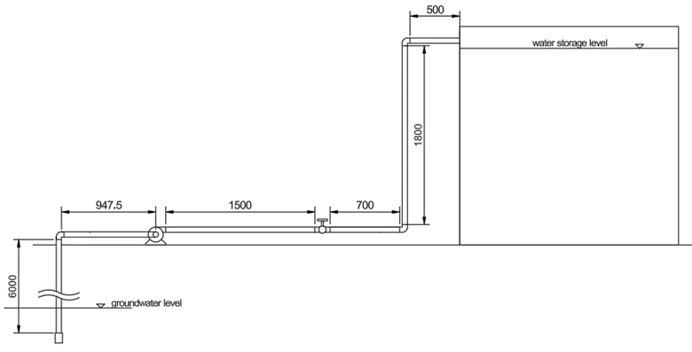
Groundwater at 25 °C is pumped to a storage tank using 1½-inch Schedule 40 commercial steel pipe as shown in Figure 1. A gate valve is installed for maintenance purposes and remains fully open during operation. A foot valve is installed at the suction line.
The elevation difference between the groundwater surface and the pipe outlet is 6.8 m. The system must deliver 100 gallons per minute (gpm). A centrifugal pump with an efficiency of 60% is used. Local atmospheric pressure is assumed to be 100 kPa.
Assumptions
- Dissolved solids in groundwater have negligible effect on water properties.
- Atmospheric pressure difference between inlet and outlet is negligible.
Mechanical Energy Balance Equation
The theoretical pump work is calculated using the mechanical energy balance:
Ws = ΔPE + ΔKE + ΔP/ρ + Ftotal
The actual pump power is calculated using pump efficiency:
Wa = Ws / η
This calculator provides a fast and reliable calculations with built-in select options for nominal size and schedule number of commercial steel pipes, and fittings and valve coefficients for faster computations.
Step-by-Step Calculator Procedure
- Input flow rate: 100 gpm
- Elevation Profile:
- Input elevation difference: 6.8 m
- Relative elevation of the liquid source -> the liquid source is below the discharge
- Select where the elevation is measured -> the elevation was measured between the source liquid surface and pipe outlet
- Pressure profile:
- Pressure 1 = 100000 Pa
- Pressure 2 = 100000 Pa
-
Pipe specification:
- Pipe material: Commercial steel
- Nominal pipe size: 1½ inch
- Schedule number: 40ST/40S
- Total pipe length: 11.4475 m
-
Fluid properties (water at 25°C & 100 kPa):
You can use Water & Steam Properties calculator to determine this. Use TP input pair with T = 298.15 K (25°C) and 0.1 MPa (100 kPa).
- Density = 995.71 kg/m³
- Viscosity = 853.83 µPa·s
-
Pump selection:
Pump type: Centrifugal pump
Efficiency: 60%Typical efficiency of pumps are provided which can be your basis in case the efficiency is not given.
-
Fittings and valves:
- Foot valve, 1 pc
- 90° elbow standard, 3 pcs
- Gate valve at 100% opening (fully open), 1 pc
Note: All added fittings and valves is display below the schematics. You can remove added fittings or valves by clicking the “x” button.
- Click Calculate Pump Power.
Results
The calculator produces the following results:
- Theoretical power = 2.227 kW (2.99 hp)
- Actual power = 3.711 kW (4.98 hp)
Therefore, a 5 hp centrifugal pump with an efficiency of 60% should be selected.
Energy Balance Terms
| Term | Value | Unit |
|---|---|---|
| Mass Flow Rate | 6.2820 | kg/s |
| Δ Kinetic Energy | 11.5365 | J/kg |
| Δ Potential Energy | 66.7080 | J/kg |
| Δ Pressure Energy | 0.0000 | J/kg |
| Pipe Friction Loss | 69.3910 | J/kg |
| Entrance Loss | 5.7683 | J/kg |
| Exit Loss | 0.0000 | J/kg |
| Fittings Loss | 201.0727 | J/kg |
| Total Friction Loss | 276.2319 | J/kg |
Hydraulic Parameters
| Parameter | Value | Unit |
|---|---|---|
| Pipe Diameter | 0.0409 | m |
| Pipe Velocity | 4.8034 | m/s |
| Reynolds Number | 2.291e+5 | - |
| Flow Regime | Turbulent | - |
| Total Loss Coefficient | 23.9441 | - |
| Pump Efficiency | 60% | - |
Engineering Insight
Although the elevation difference in this system is only 6.8 m, the largest energy loss comes from pipe friction and fitting losses. This occurs because the fluid must pass through several elbows, valves, and pipe sections that create resistance to flow.
This illustrates an important engineering principle in piping system design:
Minor losses from fittings and valves can dominate the total energy loss in a piping system.
For long piping systems with multiple fittings, the combined resistance from elbows, valves, and pipe roughness can significantly increase the pump power requirement.
Design Optimization
The operating cost of a pumping system can often be reduced by selecting the optimum pipe diameter. Larger pipes reduce friction losses but increase installation cost, while smaller pipes reduce capital cost but increase pumping energy requirements.
You can evaluate this trade-off using our Optimum Pipe Diameter Calculator .
This calculator determines the economic pipe diameter that minimizes the total lifetime cost of a piping system by balancing pipe capital cost and pumping energy cost.
Cavitation Considerations
Before selecting a pump, it is also important to verify the Net Positive Suction Head (NPSH).
If the available NPSH is insufficient, the pump may experience cavitation, which can cause serious operational problems.
Potential consequences of cavitation include:
- Cavitation bubbles inside the pump
- Excessive noise and vibration
- Impeller damage
- Reduced pump efficiency
You can evaluate this condition using our NPSH Available Calculator to ensure safe and reliable pump operation.
Example 2: Power Requirement for Pumping Molasses Between Tanks
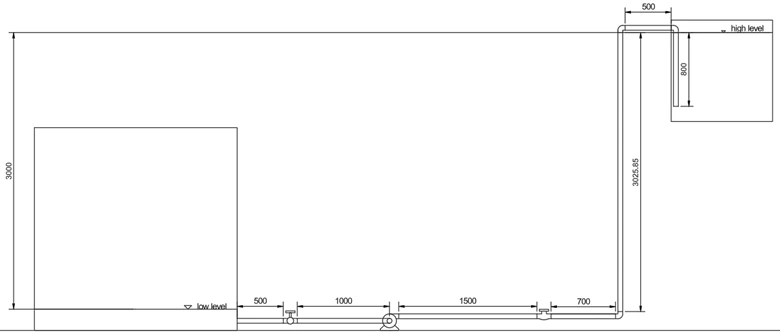
Molasses is pumped from a ground-level storage tank to an elevated receiving tank in a fermentation plant at a rate of 15 m³/h.
Because molasses is highly viscous, the discharge pipe is submerged below the receiving tank liquid level to prevent air entrainment. The system uses a rotary lobe pump with efficiency 75%.
The pipeline consists of 2 inch Schedule 40 commercial steel pipe with a diaphragm valve and ball-type check valve. The elevation difference between tanks is 3 m.
Step-by-Step Calculator Procedure
- Input flow rate: 15 m³/h
- Elevation Profile:
- Input elevation difference: 3 m
- Relative elevation of the liquid source -> the liquid source is below the discharge
- Select where the elevation is measured -> the elevation was measured between the source liquid surface (storage tank) and sink liquid surface (receiving tank) with sink velocity equal to zero
- Pressure profile:
- Toggle the atmospheric pressure in both pressure 1 and 2
-
Pipe specification:
- Pipe material: Commercial steel
- Nominal pipe size: 2 inch
- Schedule number: 40ST/40S
- Total pipe length: 8.02585 m
-
Fluid properties:
- Density = 1400 kg/m³
- Viscosity = 8000000 µPa·s
-
Pump selection:
Pump type: Rotary lobe pump
Efficiency: 75%Typical efficiency of pumps are provided which can be your basis in case the efficiency is not given.
-
Fittings and valves:
- Check valve ball, 1 pc
- 90° elbow standard, 3 pcs
- Diaphragm valve at 100% opening (fully open), 1 pc
Note: All added fittings and valves is display below the schematics. You can remove added fittings or valves by clicking the “x” button.
- Click Calculate Pump Power.
Results
- Theoretical power = 6.971 kW (9.35 hp)
- Actual power = 9.294 kW (12.46 hp)
Therefore a 12.5 hp rotary lobe pump with an efficiency of 75% should be selected.
Energy Balance Terms
| Term | Value | Unit |
|---|---|---|
| Mass Flow Rate | 5.8333 | kg/s |
| Δ Kinetic Energy | 0.0000 | J/kg |
| Δ Potential Energy | 29.4300 | J/kg |
| Δ Pressure Energy | 0.0000 | J/kg |
| Pipe Friction Loss | 1024.7197 | J/kg |
| Entrance Loss | 0.9261 | J/kg |
| Exit Loss | 1.8521 | J/kg |
| Fittings Loss | 138.0660 | J/kg |
| Total Friction Loss | 1165.5639 | J/kg |
Hydraulic Parameters
| Parameter | Value | Unit |
|---|---|---|
| Pipe Diameter | 0.0525 | m |
| Pipe Velocity | 1.9246 | m/s |
| Reynolds Number | 1.768e+1 | - |
| Flow Regime | Laminar | - |
| Total Loss Coefficient | 629.3107 | - |
| Pump Efficiency | 75% | - |
Engineering Interpretation
Several important observations can be made from the results of this pumping system.
1. Extremely Low Reynolds Number
The calculated Reynolds number is:
Re = 17.68
Since laminar flow occurs when:
Re < 2100
the flow inside the pipe is deeply laminar. This condition is typical when pumping highly viscous fluids such as molasses, syrups, and heavy oils.
2. Friction Loss Dominates the Energy Balance
The calculated pipe friction loss is 1024.72 J/kg, which is significantly larger than all other energy terms in the mechanical energy balance.
This indicates that the pump power requirement is dominated by viscous shear forces inside the pipe rather than elevation or kinetic energy changes.
3. Minor Losses Are Still Significant
Losses from fittings and valves contribute approximately:
138.07 J/kg
Although smaller than the pipe friction loss, these minor losses still represent more than 10% of the total friction losses in the system.
4. Pipe Velocity Is Moderate
The calculated pipe velocity is:
v = 1.9246 m/s
This velocity is typical for viscous fluid transport systems because it balances pressure drop, pumping power, and pipe installation cost.
Why a Rotary Lobe Pump Is Used
Centrifugal pumps often become inefficient when pumping highly viscous fluids because their performance decreases rapidly with increasing viscosity.
Positive displacement pumps such as rotary lobe pumps are typically preferred for viscous fluids because they:
- Maintain stable flow at high viscosity
- Operate efficiently under laminar flow conditions
- Provide steady, low-shear pumping
- Handle shear-sensitive fluids effectively
For these reasons, a rotary lobe pump with 75% efficiency is selected for this system.
Design Tip: Optimize Pipe Diameter
Highly viscous fluids generate very large friction losses in pipes. Increasing the pipe diameter slightly can significantly reduce the required pumping power.
You can evaluate this trade-off using our Optimum Pipe Diameter Calculator .
This tool determines the pipe diameter that minimizes the combined capital cost and operating energy cost of the pumping system.
Additional Design Check: NPSH
When designing pumping systems, engineers must also verify the Net Positive Suction Head Available (NPSHa).
If the available NPSH is lower than the pump's required NPSH, the system may experience:
- Cavitation
- Pump vibration
- Reduced efficiency
- Premature pump failure
You can evaluate this condition using the NPSH Available Calculator .
Pump Power, Head, and Energy Fundamentals in Fluid Systems
Understanding how pumps add energy to fluids is essential in fluid mechanics, piping system design, and energy optimization. In most real-world systems, fluid must be transported across elevations, through long pipelines, and against pressure requirements—tasks that cannot be achieved by gravity alone.
Pumps provide the necessary energy to overcome:
- Elevation differences (static head)
- Required discharge pressure
- Friction losses in pipes, fittings, and valves
- Velocity and flow resistance in the system
The amount of energy required is expressed as pump power, which depends on both flow rate and total system head.
Traditionally, determining pump power involves multiple steps:
- Calculating fluid velocity and Reynolds number
- Determining friction factors using correlations or Moody diagram
- Computing pipe and minor losses
- Summing all energy terms to obtain total dynamic head (TDH)
- Calculating hydraulic and actual pump power
This process can be time-consuming and iterative, especially when evaluating different pipe sizes, materials, or operating conditions.
This learning section explains the fundamental principles of pump power, head, and energy losses, helping you understand how different design parameters affect system performance and energy consumption.
By mastering these concepts, you will be able to:
- Estimate pump power requirements accurately
- Understand the relationship between head, flow rate, and energy
- Evaluate the impact of pipe diameter and roughness
- Design more efficient and cost-effective pumping systems
The sections below provide a structured explanation of pump operation, energy balance, and design considerations used in real engineering systems.
Why Do We Use Pumps?
Pumps are mechanical devices that add energy to fluids in order to move them through piping systems. They overcome elevation differences, pressure requirements, and friction losses caused by pipes and fittings.
Pumps are essential in:
- Water supply and distribution systems
- Boiler feed water systems
- Irrigation and agriculture
- Cooling water circulation
- HVAC chilled water systems
- Chemical and process industries
- Oil and fuel transfer systems
What Determines Pump Power Requirement?
Pump power depends on the total head the system requires and the desired flow rate. The total head includes elevation difference and all friction losses.
Total Head = Elevation Head + Friction Losses
Theoretical vs Actual Pump Power
Theoretical (hydraulic) power represents the ideal energy required to move the fluid:
Hydraulic Power = ρ g Q H
- ρ = fluid density
- g = acceleration due to gravity
- Q = volumetric flow rate
- H = total head required
This assumes no mechanical or hydraulic losses.
Actual pump power accounts for efficiency:
Actual Power = Hydraulic Power / Pump Efficiency
Since no pump is perfectly efficient, input power is always higher than hydraulic power. Losses occur due to mechanical friction, turbulence, leakage, and internal recirculation.
Understanding Total Dynamic Head (THD) in Pump Systems
Total Dynamic Head (TDH) represents the total equivalent head that a pump must overcome. It is independent of fluid density when expressed in meters or feet.
Head consists of:
- Static head (elevation difference)
- Pressure head
- Velocity head
- Friction losses
Pipe Friction and Minor Losses
As fluid flows through pipes, energy is dissipated due to wall friction and flow disturbances. These losses increase required pump power.
1. Pipe Friction Loss (Darcy–Weisbach):
hf = f (L/D) (V² / 2g)
2. Fitting Loss:
hfittings = K (V² / 2g)
3. Entrance Loss:
hentrance = Ke (V² / 2g)
4. Exit Loss:
hexit = Kexit (V² / 2g)
Total head loss is the sum of all frictional and minor losses.
How Does Pipe Material Affect Pump Power?
Pipe roughness influences the friction factor. Rough materials create greater turbulence in turbulent flow, increasing energy dissipation.
For the same diameter and flow rate:
- Smoother pipes → lower friction → lower pump power
- Rougher pipes → higher friction → higher pump power
Effect of Pipe Diameter on Pump Power
Velocity is inversely proportional to pipe cross-sectional area. Smaller diameters increase velocity and friction loss.
- Small diameter → high velocity → high friction → higher power
- Large diameter → lower velocity → lower friction → lower power
However, larger pipes increase capital cost, which is why economic optimization is important in system design.
What is Pump Efficiency?
Pump efficiency is the ratio of hydraulic power delivered to the fluid to the mechanical power supplied to the shaft.
Efficiency varies with flow rate and is typically highest near the Best Efficiency Point (BEP).
Operating far from BEP reduces efficiency and increases energy cost.
How Does Flow Rate Affect Pump Power?
Pump power generally increases with flow rate because:
- Velocity increases
- Friction losses increase approximately with V²
- Total head demand increases
Proper sizing ensures the pump operates efficiently at the required duty point.
Common Causes of Excessive Pump Power Consumption
- Undersized piping
- Excessive fittings and valves
- Rough or aged pipe material
- Operating far from design point
- Cavitation or internal recirculation
Types of Pumps and Power Characteristics
Different pump types exhibit different power-flow relationships.
Dynamic Pumps
Dynamic pumps (e.g., centrifugal pumps) generate head by increasing fluid velocity. Power typically rises with increasing flow rate.
Positive Displacement Pumps
Positive displacement pumps move a fixed volume per cycle. Power requirement depends more strongly on discharge pressure than on flow rate.
Why Accurate Pump Power Calculation Matters
Accurate pump power estimation ensures:
- Proper motor selection
- Energy efficiency
- Reduced operational cost
- Improved system reliability
- Compliance with energy standards
Even small inefficiencies can lead to significant energy costs over the lifetime of the system.
Step-by-Step Pump Power Calculation Method
- Determine flow rate (mass or volumetric).
- Calculate fluid velocity based on pipe diameter.
- Determine Reynolds number and friction factor.
- Compute pipe friction loss using Darcy–Weisbach equation.
- Add minor losses from fittings and valves.
- Add elevation and pressure head differences.
- Calculate total dynamic head (TDH).
- Compute hydraulic power using ρgQH.
- Divide by pump efficiency to obtain actual shaft power.
How to Select the Correct Motor Power for a Pump
Motor power must exceed the calculated shaft power to account for:
- Service factor
- Starting torque requirements
- Voltage variation
- Mechanical losses
A common engineering practice is to select a motor 10–15% higher than the calculated shaft power.