Tank Elevation Calculator for Gravity-Driven Flow Systems
Elevated storage tanks are widely used in water distribution systems, agricultural irrigation, and industrial fluid transport to provide flow without the need for continuous pumping. By placing the tank at a higher elevation, gravitational potential energy is converted into pressure and velocity, allowing fluid to flow through pipelines.
The required tank elevation (height) must be sufficient to overcome:
- Desired outlet pressure
- Fluid acceleration (kinetic energy)
- Friction losses in pipes, fittings, and valves
If the elevation is too low, the system may fail to deliver the required flow rate or pressure. If it is too high, unnecessary construction and structural costs are incurred.
Traditional Method of Calculating Tank Elevation
Conventionally, determining the required tank elevation involves applying the mechanical energy balance equation and performing multiple manual calculations:
- Estimating pipe velocity from flow rate
- Calculating Reynolds number and flow regime
- Determining friction factor using correlations or Moody diagram
- Evaluating pipe, fittings, entrance, and exit losses
- Iteratively solving for elevation due to dependence on velocity
This process can be time-consuming and prone to error, especially when evaluating multiple design scenarios or pipe sizes.
Advantages of This Tank Elevation Calculator
This calculator automates the complete energy balance analysis and provides fast, accurate results for engineering design and evaluation.
- Automatic calculation of all energy balance terms
- Integrated pipe friction and minor loss modeling
- Built-in commercial steel pipe database
- Fittings and valve loss coefficient library
- Automatic flow regime and Reynolds number evaluation
- Results with detailed energy breakdown and hydraulic parameters
This allows engineers and students to quickly analyze how flow rate, pipe diameter, and system configuration affect the required tank elevation.
How to Use the Tank Elevation Calculator
- Enter the required flow rate (mass or volumetric).
- Define the pressure conditions at the tank surface and pipe outlet.
- Specify pipe material, diameter, and total length.
- Input fluid properties (density and viscosity).
- Add fittings and valves from the built-in database.
- Click "Calculate Required Elevation" to determine the minimum tank height.
- Refine the pipe length (including vertical sections) and iterate if necessary for accurate design.
This tool is ideal for preliminary design, educational purposes, and system optimization in gravity-driven piping systems.
System Inputs
System Schematic
Results
Energy Balance Terms
Hydraulic Parameters
Worked Examples: Tank Elevation in Piping Systems
The following worked examples demonstrate how to determine the required tank elevation using the mechanical energy balance equation. These examples are designed for students, engineers, and designers who want to understand how flow rate, pipe diameter, and friction losses affect system performance.
In gravity-driven systems, the tank elevation provides the necessary potential energy (head) to overcome:
- Required outlet pressure
- Fluid acceleration (kinetic energy)
- Friction losses in pipes, fittings, and valves
Traditionally, solving these problems requires:
- Manual application of the energy balance equation
- Iterative calculation of friction factors
- Estimation of losses from fittings and valves
- Repeated trial-and-error to determine elevation
This calculator simplifies the process by automatically computing all energy terms, allowing rapid evaluation of different design scenarios.
What You Will Learn from These Examples
- Example 1: Determining tank elevation for a low-flow system where pressure requirements dominate
- Example 2: Understanding how increasing flow rate significantly increases friction losses and required elevation
- Example 3: Evaluating the effect of pipe diameter on reducing friction losses and improving system efficiency
Key Engineering Insight
These examples highlight a fundamental principle in fluid mechanics:
Required elevation (or pump head) is influenced by both pressure requirements and friction losses, and their relative importance depends on flow rate and pipe diameter.
By analyzing these scenarios, engineers can make informed decisions on:
- Pipe sizing
- Tank height selection
- Energy efficiency optimization
- Pump integration when elevation is insufficient
For cost optimization, you may also use the Optimum Pipe Diameter Calculator , and for pump sizing, refer to the Pump Power Calculator .
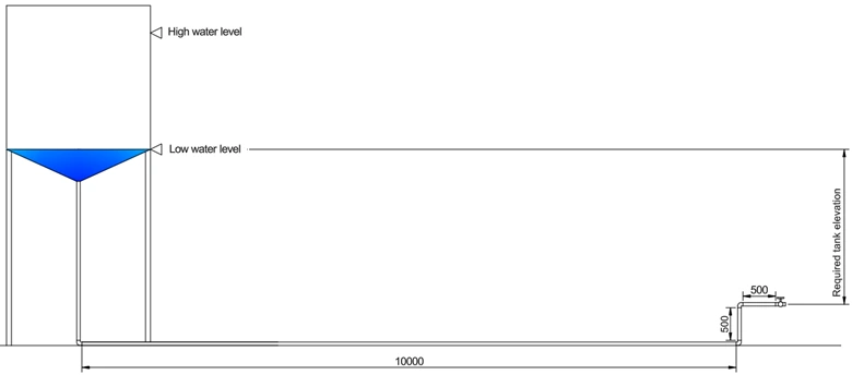
Example 1: Required Minimum Elevation for a Water Storage Tank
A water storage tank is installed to supply water to a greenhouse system. The pipeline consists of a 2-inch Schedule 40 commercial steel pipe with a gate valve as shown in the figure.
Determine the minimum required elevation of the tank (measured from the low level of the tank to the pipe outlet centerline) to sustain:
- Flow rate = 10 gpm
- Outlet pressure = 50 kPa (gauge)
Assume water at 25°C and atmospheric pressure of 100 kPa.
Solution
The required tank elevation corresponds to the vertical distance between the lowest operating water level and the pipe outlet.
The mechanical energy balance equation is:
Ws = ṁ(ΔPE + ΔKE + ΔP/ρ + Ftotal)
Since there is no pump in the system:
ΔPE + ΔKE + ΔP/ρ + Ftotal = 0
Taking:
- Point 1 → water surface (v₁ ≈ 0)
- Point 2 → pipe outlet (reference height = 0)
The equation becomes:
g(0 − hreq) + ½(v₂² − 0) + (P₂ − P₁)/ρ + Ktotal(v₂²/2) = 0
Solving for required elevation:
hreq = (v₂² / 2g)(1 + Ktotal) + (P₂ − P₁)/(ρg)
Loss Coefficients
Total loss coefficient:
Ktotal = Kentrance + Kfittings + Kpipe + Kexit
Entrance loss:
Note: Diameter of the tank >> diameter of the pipe, A2/A1 ≈ 0.
Kentrance = 0.5(1 − A₂/A₁) ≈ 0.5
Fittings & Valve losses:
Friction coefficients for fittings and valves are obtained from a built-in database within the calculator. Users can select the appropriate components and specify their quantities, allowing automatic calculation of the total fittings loss.
Exit loss:
The exit loss is taken as zero because the pipe outlet is defined as the reference point (Point 2) in the energy balance analysis.
Pipe friction:
Kpipe = 4fL/D
The Fanning friction factor is determined automatically using:
- Laminar: fF = 16/Re
- Turbulent: Churchill (1977) Approximation of the Colebrook Equation
- ε = pipe roughness (m)
- D = pipe diameter (m)
- Re = Reynolds number
- Transition: unified Churchill correlation
1 / √fF = −4 log₁₀[(0.27 ε / D) + (7 / Re)0.9]
where:
fF = 2 [(8 / Re)12 + 1 / (A + B)3/2]1/12
where:
A = {2.457 ln [1 / ((7 / Re)0.9 + (0.27 ε / D))]}16
B = (37530 / Re)16
These are handled internally by the calculator.
Step-by-Step Procedure
- Flow rate: 10 gpm
-
Pressure profile:
- P₁ = 100,000 Pa
- P₂ = 150,000 Pa
-
Pipe specification:
- Material: Commercial steel
- Size: 2 in
- Schedule: 40ST/40S
- Initial length: 11 m
-
Fluid properties:
Use Water & Steam Properties Calculator
(TP mode: 298.15 K, 0.1 MPa)- density = 995.71 kg/m³
- viscosity = 853.83 µPa·s
-
Add fittings:
- 3 pcs × 90° elbows
- 1 pc × fully open (100%) gate valve
Note: All added fittings and valves is display below the schematics. You can remove added fittings or valves by clicking the “x” button.
- Click Calculate Required Elevation
- Update pipe length to include vertical section: Final length = 16 m
- Recalculate
Results
The calculated minimum required elevation is 5.17 m. In practical engineering design, this value should be rounded up to account for uncertainties and future system variations.
Therefore, a design elevation of: 5.2 m is recommended.
This additional margin ensures that the system can reliably maintain the required flow rate and outlet pressure even under non-ideal conditions such as:
- Pipe roughness increase due to aging or fouling
- Minor additional fittings or valves not included in the model
- Flow fluctuations or transient operating conditions
- Measurement and estimation uncertainties
Providing a small safety allowance is a standard engineering practice to ensure consistent performance and avoid underdesign.
Energy Balance Breakdown
The calculator provides a detailed breakdown of each term in the mechanical energy balance equation. These values help identify which components contribute most to the required tank elevation.
| Term | Value | Unit |
|---|---|---|
| Mass Flow Rate | 0.6282 | kg/s |
| Δ Kinetic Energy | 0.0425 | J/kg |
| Δ Potential Energy | -50.7513 | J/kg |
| Δ Pressure Energy | 50.2154 | J/kg |
| Pipe Friction Loss | 0.3691 | J/kg |
| Entrance Loss | 0.0212 | J/kg |
| Exit Loss | 0.0000 | J/kg |
| Fittings Loss | 0.1032 | J/kg |
| Total Friction Loss | 0.4934 | J/kg |
Hydraulic Parameters
| Parameter | Value | Unit |
|---|---|---|
| Pipe Diameter (D) | 0.0525 | m |
| Pipe Velocity (v) | 0.2914 | m/s |
| Reynolds Number | 1.784e+4 | — |
| Flow Regime | Turbulent | — |
| Total Loss Coefficient (ΣK) | 11.6204 | — |
| Required Elevation (Δz) | 5.1734 | m |
Interpretation of Results
The energy balance results provide important insight into how the required tank elevation is distributed among different energy components.
1. Pressure Energy Dominates the System
The required outlet pressure contributes
50.2154 J/kg, which is almost equal in magnitude to the
required elevation energy (50.7513 J/kg).
This indicates that the primary purpose of the tank elevation is to generate pressure head, rather than to overcome friction losses.
2. Friction Losses Are Very Small
The total friction loss is only
0.4934 J/kg, which is less than 1% of the total energy requirement.
This occurs because:
- The pipe velocity is low (0.29 m/s)
- The pipe diameter is relatively large
- The pipeline length is short
Thus, friction has minimal effect on the required elevation.
3. Kinetic Energy Contribution Is Negligible
The kinetic energy term is only
0.0425 J/kg, which is very small compared to pressure and potential energy.
This confirms that velocity effects are insignificant in this system.
4. Flow Regime Is Turbulent
The Reynolds number is 1.78 × 10⁴, indicating turbulent flow.
However, due to low velocity, turbulence does not significantly increase friction losses.
Key Engineering Insight
This example demonstrates an important design principle:
When flow velocity is low, pressure requirements dominate system design, and friction losses become negligible.
In such systems, increasing pipe diameter will have little effect on required elevation because friction losses are already minimal.
Design Implications
- Elevation-driven systems should be designed primarily based on pressure requirements rather than friction losses.
- Increasing pipe diameter will yield minimal benefit in this case, since friction losses are already very small.
- If elevation is constrained, a pump may be required to supply the necessary pressure head.
Design Notes
1. Pipe Diameter Optimization
Using a larger pipe diameter reduces friction losses and may slightly
reduce required elevation. Evaluate this using the
Optimum Pipe Diameter Calculator
.
2. Pump Integration
If elevation is limited, a pump can be used instead.
Determine the required pump power using the
Pump Power Calculator
.
3. Practical Design Allowance
Always include a safety margin (5–10%) in elevation to account for:
- Future pipe roughness increase
- Additional fittings
- Flow variability
Example 2: Effect of Increased Flow Rate on Required Tank Elevation
The greenhouse system in Example 1 expands its operation and now requires a higher flow rate of 100 gpm.
Using the same pipe diameter (2-inch Schedule 40 commercial steel), determine the new required tank elevation.
Step-by-Step Procedure
- Input flow rate: 100 gpm
-
Pressure profile:
- P₁ = 100,000 Pa
- P₂ = 150,000 Pa (50 kPa gauge + atmospheric pressure)
-
Pipe specifications:
- Material: Commercial steel
- Nominal pipe size: 2 in
- Schedule: 40
- Initial pipe length: 11 m
-
Fluid properties:
Use the Water & Steam Properties Calculator (TP mode: 298.15 K, 0.1 MPa)- density = 995.71 kg/m³
- viscosity = 853.83 µPa·s
-
Add fittings and valves:
- 3 × 90° elbows
- 1 × fully open gate valve
-
Click Calculate Required Elevation
→ Initial result: 8.7087 m - Estimate vertical pipe length ≈ 8.5 m → update total pipe length: 19.5 m
- Recalculate → elevation = 10.1684 m
- Refine vertical length to 10 m → total pipe length: 21 m
- Final calculation → required elevation: 10.4260 m → Use 10.5 m
Energy Balance Terms
| Term | Value | Unit |
|---|---|---|
| Mass Flow Rate | 6.2820 | kg/s |
| Δ Kinetic Energy | 4.2464 | J/kg |
| Δ Potential Energy | -102.2791 | J/kg |
| Δ Pressure Energy | 50.2154 | J/kg |
| Pipe Friction Loss | 35.3788 | J/kg |
| Entrance Loss | 2.1232 | J/kg |
| Exit Loss | 0.0000 | J/kg |
| Fittings Loss | 10.3153 | J/kg |
| Total Friction Loss | 47.8173 | J/kg |
Hydraulic Parameters
| Parameter | Value | Unit |
|---|---|---|
| Pipe Diameter (D) | 0.0525 | m |
| Pipe Velocity (v) | 2.9142 | m/s |
| Reynolds Number | 1.784e+5 | — |
| Flow Regime | Turbulent | — |
| Total Loss Coefficient (ΣK) | 11.2608 | — |
| Required Elevation (Δz) | 10.4260 | m |
Engineering Insight
Increasing the flow rate from 10 gpm to 100 gpm results in a dramatic increase in required elevation (from approximately 5.2 m to 10.5 m).
This occurs because:
- Velocity increases significantly (0.29 → 2.91 m/s)
- Friction losses increase approximately with v²
- Total friction loss becomes comparable to pressure requirements
Unlike Example 1, where pressure dominated, this system is now strongly influenced by pipe friction losses.
At high flow rates, friction losses can become the dominant factor in determining required elevation or pump head.
Design Notes
1. Pipe Diameter Optimization
The high friction loss (47.82 J/kg) indicates that the pipe is
undersized for this flow rate.
Using a larger pipe diameter can significantly reduce the required elevation. Evaluate this using the Optimum Pipe Diameter Calculator .
2. Pump-Assisted Systems
If increasing tank elevation is impractical, a pump may be used instead.
Determine the required pump power using the
Pump Power Calculator
.
3. Velocity Consideration
The velocity (~2.9 m/s) is near the upper limit of typical design ranges.
High velocities increase:
- Energy consumption
- Pipe wear and noise
- Operating cost
Reducing velocity through larger pipe diameter improves long-term efficiency.
Example 3: Effect of Pipe Diameter on Required Tank Elevation
Consider the system in Example 2, but instead of using a 2-inch pipe, a larger 3-inch Schedule 40 commercial steel pipe is used.
Determine how increasing the pipe diameter affects the required tank elevation for a flow rate of 100 gpm.
Step-by-Step Procedure
- Input flow rate: 100 gpm
-
Pressure profile:
- P₁ = 100,000 Pa
- P₂ = 150,000 Pa (50 kPa gauge + atmospheric pressure)
-
Pipe specifications:
- Material: Commercial steel
- Nominal pipe size: 3 in
- Schedule: 40
- Initial pipe length: 11 m
-
Fluid properties:
Use the Water & Steam Properties Calculator (TP mode: 298.15 K, 0.1 MPa)- Density = 995.71 kg/m³
- Viscosity = 0.00085383 Pa·s
-
Add fittings and valves:
- 3 × 90° elbows
- 1 × fully open gate valve
Note: All added fittings and valves are displayed below the schematic. You can remove them by clicking the “x” button.
-
Click Calculate Required Elevation
→ Initial result: 5.7254 m - Estimate vertical pipe length ≈ 5.5 m → update total pipe length: 16.5 m
- Recalculate → elevation = 5.8535 m
- Refine vertical pipe length to 5.7 m → total pipe length: 16.7 m
- Final calculation → required elevation: 5.8582 m → Use 5.9 m
Energy Balance Terms
| Term | Value | Unit |
|---|---|---|
| Mass Flow Rate | 6.2820 | kg/s |
| Δ Kinetic Energy | 0.8749 | J/kg |
| Δ Potential Energy | -57.4690 | J/kg |
| Δ Pressure Energy | 50.2154 | J/kg |
| Pipe Friction Loss | 3.8159 | J/kg |
| Entrance Loss | 0.4374 | J/kg |
| Exit Loss | 0.0000 | J/kg |
| Fittings Loss | 2.1253 | J/kg |
| Total Friction Loss | 6.3786 | J/kg |
Hydraulic Parameters
| Parameter | Value | Unit |
|---|---|---|
| Pipe Diameter (D) | 0.0779 | m |
| Pipe Velocity (v) | 1.3228 | m/s |
| Reynolds Number | 1.202e+5 | — |
| Flow Regime | Turbulent | — |
| Total Loss Coefficient (ΣK) | 7.2907 | — |
| Required Elevation (Δz) | 5.8582 | m |
Engineering Insight
Increasing the pipe diameter from 2 inches to 3 inches significantly reduces the required tank elevation from approximately 10.5 m (Example 2) to 5.9 m.
This improvement is primarily due to:
- Reduced fluid velocity (2.91 → 1.32 m/s)
- Lower friction losses (from 47.82 J/kg → 6.38 J/kg)
- Decreased total loss coefficient (ΣK)
Since friction losses are proportional to approximately v², even a moderate reduction in velocity leads to a large reduction in energy loss.
Increasing pipe diameter is one of the most effective ways to reduce energy losses and required system head in fluid transport systems.
Design Notes
1. Trade-off Between Capital and Operating Cost
Larger pipes reduce friction losses and required elevation,
but increase installation cost. Engineers must balance these factors.
Use the Optimum Pipe Diameter Calculator to determine the most economical pipe size.
2. Pump Selection Consideration
Lower required elevation translates to lower pump head and energy consumption.
If a pump is used, calculate the required power using the
Pump Power Calculator
.
3. Recommended Velocity Range
The new velocity (~1.32 m/s) falls within the typical economic range
(1–3 m/s), resulting in:
- Lower energy losses
- Reduced noise and vibration
- Improved system efficiency
This demonstrates that proper pipe sizing is critical for efficient and sustainable system design.
Common Tank Elevation Calculation Questions
- How high should a water tank be for gravity flow?
- How much height is needed to create water pressure?
- How do you calculate gravity feed flow rate?
- What elevation produces 1 bar of pressure?
- How to size an elevated water tank?
Pressure generated by elevation is:
P = ρ g h
For water, approximately:
1 meter ≈ 9.81 kPa
10 meters ≈ 0.98 bar
Fundamentals of Tank Elevation and Gravity-Driven Flow Systems
Understanding how tank elevation affects fluid flow is essential in designing gravity-driven piping systems used in water supply, irrigation, and industrial applications.
In these systems, the elevation of the tank determines how much pressure and flow rate can be delivered without continuous pumping. Engineers must ensure that the available gravitational head is sufficient to overcome:
- Required outlet pressure
- Pipe friction losses
- Losses from fittings and valves
- Changes in elevation along the pipeline
Traditionally, evaluating tank elevation requires applying the mechanical energy balance equation, calculating Reynolds number, estimating friction factors, and summing multiple loss components. This process can become complex and iterative, especially for systems with varying pipe lengths and configurations.
This learning section explains the fundamental principles behind tank elevation and gravity flow, helping you understand how different design variables—such as flow rate, pipe diameter, and material—affect system performance.
By mastering these concepts, you will be able to:
- Estimate required tank height for gravity systems
- Understand the relationship between elevation and pressure
- Evaluate the impact of pipe size and friction losses
- Design more efficient and reliable fluid transport systems
The sections below provide a step-by-step explanation of these concepts, from basic principles to practical engineering considerations.
Why Do We Use Elevated Tanks?
Elevated tanks store fluid at a higher elevation to generate pressure using gravity. By raising the liquid level, potential energy is converted into pressure head, allowing fluid to flow without continuous pumping.
Elevated tanks are commonly used in:
- Municipal water distribution systems
- Irrigation networks
- Industrial process plants
- Fire protection systems
They provide passive pressure generation and improve overall system reliability.
Advantages of Elevated Storage Tanks
- Reduced energy consumption during distribution
- Backup water supply during power outages
- Pressure stabilization across large areas
- Lower long-term operating cost
Is Using an Elevated Tank Better Than Using Pumps?
Pumps offer flexibility and high discharge pressure, but require continuous power and maintenance.
Elevated tanks:
- Reduce continuous pumping requirements
- Improve system resilience
- Provide steady gravity-driven flow
Most practical systems combine both approaches: pumps fill the tank, and gravity distributes the fluid.
Why Must Gravity Tanks Be Elevated?
Fluid flows from regions of higher energy to lower energy. Elevation increases static head:
Static Head = Elevation Difference
Without sufficient elevation, gravity alone cannot overcome pipe friction and required discharge pressure.
What Determines the Required Tank Height?
The required tank elevation must overcome:
- Static elevation difference
- Pipe friction losses
- Minor losses (fittings, bends, valves)
- Entrance and exit losses
- Minimum required discharge pressure
Total required head:
Tank Elevation = Static Requirement + Total Head Loss
How is Flow Rate Related to Tank Elevation?
In gravity-driven systems, flow rate depends on the available head. Higher tank elevation increases pressure at the pipe inlet, which increases velocity and flow rate.
For turbulent flow:
Head Loss ∝ V²
This means small increases in velocity significantly increase friction losses.
How Do Pipe Material and Diameter Affect Required Tank Height?
Pipe roughness affects the friction factor. Rougher pipes increase energy loss and require higher tank elevation.
Pipe diameter strongly influences velocity:
- Smaller diameter → higher velocity → higher friction loss
- Larger diameter → lower velocity → lower friction loss
Selecting proper pipe size reduces the required tank height and improves system efficiency.
What Happens If Tank Elevation is Too Low?
- Reduced flow rate
- Insufficient downstream pressure
- Inability to overcome friction losses
- Unstable system performance
Can Tank Elevation Be Too High?
Excessive elevation increases:
- Structural construction cost
- Mechanical stress on piping
- Risk of excessive pressure at lower elevations
Pressure reducing valves may be required in tall distribution systems.
How Does Elevation Affect Pressure?
Pressure due to elevation can be estimated as:
Pressure = ρ g h
Where h is elevation difference. Each meter of water column produces approximately 9.81 kPa of pressure.
When Should a Gravity System Be Preferred?
Gravity systems are preferred when:
- Energy efficiency is a priority
- Power reliability is uncertain
- Large distribution areas require stable pressure
- Operating cost must be minimized
How Does Tank Elevation Improve System Reliability?
Elevated storage decouples supply from demand. Water can be pumped during low-demand periods and stored, then distributed during peak usage without continuous pumping.
This reduces pump cycling and extends equipment life.